
Ford 7.3L Injector Drive Module (IDM) Operation
- May 25, 2022
- 6 min read
Updated: Apr 23, 2024
The Ford Power Stroke 7.3L engine has established its legacy as a reliable and stout diesel engine. Over two million of the engines were produced from 1994 through 2003. It was replaced with the 6.0L Power Stroke engine in 2003 because it could not meet new federal emission standards.
Because of their proven track record as being a solid long lasting engine, the repair market for the Ford Power Stroke 7.3L engines is quite healthy. As with any high production vehicle, problems can and will occur. One area for potential repairs is the Injector Driver Module, or “IDM”.
The 7.3L utilizes Hydraulically actuated Electronically controlled Unit Injectors, commonly referred to as HEUI or “HUEY” injectors. These injectors utilize high pressure oil which is controlled by a poppet valve inside the injector to achieve injection pressures of up to 21,000 psi. The poppet valve operation is electronically controlled by an injector mounted solenoid.
Because of the high pressures involved, the solenoid-operated poppet valve requires 115 volts at up to 8 amps to operate, which is more power than the Powertrain Control Module (PCM) can provide. Because of this, the injectors are directly controlled by a separate control module called the Injector Driver Module (IDM). The IDM provides the high voltage and switching signals to turn the injectors on and off.
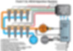
The IDM and PCM work together to control the entire fuel system (see Figure 1). The PCM receives inputs from numerous sensors then transmits injection timing signals to the IDM module, which then carries out the activation of the injectors.
Injector Power & Ground
The injectors are grouped into two banks of four injectors each. Each bank shares a common power feed which is generated by the IDM. The voltage supplied to the injectors is 115 volts DC and is only activated when one of the injectors is firing.
The injectors have 8 individual ground circuits. An injection event occurs when the IDM supplies power to the bank for the injector to be fired while simultaneously grounding the desired injector's ground circuit. The pulse supplied to the solenoid is typically between .5-2.0 milliseconds.
Injection Fuel Volume
Unlike gasoline injectors or other electronically controlled diesel injectors, the fuel volume is not controlled by the pulse width that is supplied to the injector. Instead, fuel volume is controlled by the oil pressure supplied to the injector, referred to as the Injection Control Pressure (ICP).
Oil pressure is supplied to the injector by a mechanically driven injection pump (A) at pressures of up to 3,000 psi. The injector is also supplied fuel at approximately 40-50 psi (B). Separation between the fuel and oil is accomplished with internal and external o-rings.
When the solenoid is activated the high pressure oil is supplied to the top of an internal intensifier piston, which acts upon a fuel plunger causing the fuel to be injected. The intensifier piston has an area that is seven times larger than the fuel plunger. Because of this, the pressure on the plunger is amplified to achieve injection pressures of up to 21,000 psi.
The Injection Control Pressure (ICP) is closed-looped controlled by the PCM. The PCM monitors the ICP Sensor (C) and modulates the ICP Regulator (D) to achieve the desired control pressure for the current operating condition. The fuel volume injected is directly proportional to the injection control pressure. The PCM monitors numerous input sensors to calculate the fuel demand including the Accelerator Pedal Position sensor, Engine Coolant Temperature sensor and Manifold Absolute Pressure to name a few.
Injection Timing and Synchronization
In order for the IDM to synchronize the injection events to crankshaft position it must communicate with the PCM.
The PCM generates two digital control signals for the IDM: the Fuel Delivery Control Signal (F) and the Cylinder Identification (G). The FDCS signal is used by the IDM to control injection timing and duration. The CID signal provides synchronization to the engine's first and fifth injector.
Cylinder Identification Signal (CID)
The PCM receives engine rotational position information from the Camshaft Position sensor (CMP). The CMP (E) is a hall-effect device. It outputs 12 volts to the PCM whenever it detects the iron of a spoke on the target wheel in front of it. It outputs 0 volts whenever it detects the space between the spokes. The target wheel spokes and spaces are each 15 crank degrees apart, except for narrow spoke which indicates cylinder number 1 and a wide spoke which indicates cylinder number 4 (fifth in firing order).
The PCM receives the Camshaft Position signal and transmits a modified signal (G) to the IDM that indicates which injector bank should be firing. Bank 1 consisting of cylinders 1, 3, 5 and 7 is located on the passenger side while bank 2 consisting of cylinders 2, 4, 6 and 8 is located on the driver's side. The IDM uses this signal to determine which high side driver should be switched on.
Fuel Delivery Control Signal (FDCS)
Actual injector timing and duration is controlled by the Fuel Delivery Controlled Signal. The PCM generates and transmits a pulse for each injection event (F) to the IDM. The IDM uses this signal to turn on the proper low side driver for the injector being activated.
The IDM is programmed with the firing order of the vehicle. Using both the CID and FDC signals from the PCM the IDM provides precise synchronization of injection events to piston position.
Self Diagnostics
The IDM monitors the injector switching circuits and can transmit diagnostic information to the PCM if it detects a fault (H). The PCM will store a Diagnostic Trouble Code (DTC) specific to the type of failure, which can be retrieved using the appropriate diagnostic equipment. There are numerous diagnostic codes related to the IDM so consult the vehicle specific service information for a definition of each code.
Failure Modes
The IDM module is mounted in the engine compartment and due to its location is very susceptible to water damage. Water intrusion takes place through an air vent that is an integral part of the IDM case. Once water enters the module, failure is eminent and usually results in a no-start condition. On units remanufactured by GB the vent has been redesigned to prevent this type of failure.
Another failure mode is the result of failed wiring between the IDM and the injectors. The fuel injectors on the 7.3L are located under the valve covers. Because of this, the wires for each bank of injectors pass through connectors that are molded into the valve cover gaskets. The wiring on the inside of the valve covers are constantly exposed to hot oil. Over time these connectors can become brittle and crack causing the wires to short together causing IDM failure. This type of failure must be diagnosed PRIOR to replacing the IDM; otherwise failure of the replacement module will result. Additionally, these poor connections can be intermittent so a visual inspection and electrical test is recommended prior to condemning or replacing an IDM. Intermittent connections can be difficult to diagnose and can result in intermittent injector fire either on a single injector or an entire bank. Failure to locate this type of failure can result in costly warranty come-backs. In order to properly inspect the wiring to the injectors the valve covers should be removed. It is a best practice to replace the valve cover gaskets when reinstalled if they are the original gaskets. GB has published Tech Bulletin TB#103 that details the tests that should be performed prior to replacement. The bulletin can be downloaded here.
Replacement Tips and Warnings
The actual replacement of the IDM is not technically challenging, however proper diagnosis to eliminate damage to the new IDM is critical. Here are some tips that can help:
Check for Diagnostic Trouble Codes (DTC). Follow the appropriate service manual tests for each DTC retrieved.
Perform a thorough visual inspection on the wiring between the IDM and the injectors. Flexing and wiggling the wiring harness can detect some faults and should be performed during the pin point test detailed in TB# 103.
Inspect the connectors at the valve cover gaskets both on the inside and outside. Make sure the connectors, wires and seals are not broken or soft.
Inspect the outside of the IDM. If there is corrosion present or the paint is peeling off, chances are the IDM has internal water damage. If the aluminum vent cover is missing then water damage is highly probable.
Use caution when working on the IDM system. High voltage is present on the injector wires when the engine is running (115 volts). These wires are shielded and piercing the wires will result in wiring harness damage not to mention personal injury.
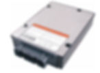
GB offers two part numbers to cover all 7.3L Power Stroke applications from 1994 through 2003. 1994-98 model years use part number 921-110 while 1999-2003 utilize GB part number 921-120. Another quick way to identify the IDM is by color. If the OE module is silver or bare aluminum it is the early module (921-110) while the 921-120 version is black.
GB also provides rebuild & return (R&R) services for customers. Please contact us for more information.
Curious to learn more? Visit our Knowledge Center, packed with fuel injection-related articles and topics to assist you in better understanding fuel injection systems and technologies.